|
|
| |||||||||||||||||||||||||||||||||||||||||||||||||||||||||||||||||||||||||||||||||||||||||||||||||
|
|
| |||||||||||||||||||||||||||||||||||||||||||||||||||||||||||||||||||||||||||||||||||||||||||||||||
|
| Technical Description | |||||||||||||||||||||||||||||||||||||||||||||||||||||||||||||||||||||||||||||||||||||||||||||||||
|
|
| |||||||||||||||||||||||||||||||||||||||||||||||||||||||||||||||||||||||||||||||||||||||||||||||||
|
|
| |||||||||||||||||||||||||||||||||||||||||||||||||||||||||||||||||||||||||||||||||||||||||||||||||
|
|
 Although the class M61 locomotives are considered first generation diesels, as are their American and Australian predecessors, some of their construction details are still of much better design (and much higher quality) than those of other Hungarian diesel power, often exclaimed more modern by some officials. Of course, their EMD 567D1 prime mover has long since been surpassed by newer, and beyond doubt, better models; of course, modular electric equipment, AC/AC transmission and other achievments opened new vistas of diesel-electric traction; of course no Flexicoil and Flexifloat truck can be a match for EMD's radial trucks, but given the real conditions in Hungary, the M61 class can still be considered the best of its kind on Hungarian rails. The reasons for this can be seen if we take a closer look inside the locomotive.
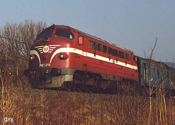
Carbody Construction As the majority of EMD cab units, the M61 class locomotives are also built with the entire carbody (underframe plus side wall bracing) being a full load-bearing structure, allowing a lightweight construction. This design principle has now been a tradition for decades and is still applied, thinking of the recently introduced British class 67. An example of a locomotive of comparable power built on a heavy underframe rather than a girder structure, is, to stick with Hungarian motive power, the M62 class; approximately 10 tons heavier than the M61, the latter even having an additional steam generator as opposed to the M62. At each end of the locomotive, an engineer's cab in the classic EMD bulldog nose design is welded to the underframe, the latter consisting of cross members and longitudinal beams, ending in the buffer beams. The side walls are made of corrugated plate steel and welded to the side bracing (as opposed to the removable riveted plates of American and Australian ancestors). Removable hatches and a removable cross member over the engine room allow easy access to machinery. The engine room itself has a very compact design with the coolers mounted above the prime mover, thus reducing the length of the locomotive, but it is still less cluttered than that of, say, an M62. The space beneath the underframe and between the three-axle trucks is occupied by the battery boxes, the air reservoirs and the fuel tanks, each of the latter equipped with a fuel fill and a fuel gauge. The fuel fills are well-protected against the tilting of the locomotive, an advantage which cannot be said of the M62 and M41 which regularly spill fuel in some critical curves, certainly not very favorable for the environment. Engineer's Cabs An engineer's cab, following EMD's bulldog nose design, is mounted on each end of the locomotive. The "nose" provides unparalleled protection in case of a collision. The entire cab is located higher than on most domestic locomotives, providing good sight and safety. The aesthetical aspect of this construction also deserves mentioning, especially because the latter was hardly considered in the domestic locomotive design of the last few decades. Unfortunately, the streamlined cab was rarely thought of in European locomotive design either, although at least additional collision protection can be observed in a number of recent constructions. 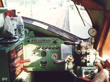 The arrangement of the control instruments follows the classical EMD setup of the 1960's and despite of its age, it is safer and more ergonomical than many of the "modern" designs. To the left of the engineer's seat, the throttle and the reverser can be found in a more or less standard EMD roller switch controller box. On the same axle as the throttle lever, a throttle wheel is also mounted, placed on top of the controller box. This was a custom design, among NOHAB-built AA16's unique to Hungary, but the controller wheel was hardly ever used in practice. The advantage of a throttle lever instead of a wheel is obvious; the throttle position can be seen more easily. The drawback of the throttle wheel can be illustrated by an accident which led to the early demise of M61-009. This locomotive was pushed through the wall of a locomotive shed by an M62 whose throttle (wheel type, of course) accidentally remained in position 1. For throttle wheels, a dial or a display behind a small window shows the throttle position, but neither of them is the "top notch" in visibility, so that the engineer often has to put up with a guess... certainly not the safest solution, especially for locomotives with much more throttle positions than 8 on EMD locomotives.
The instrument panel with the main generator ammeter, air pressure displays, switches etc. is mounted ahead of the engineer's seat in an inclined position. It is often said that the relatively large distance from the engineer and the lack of a protruding edge provides more safety in case of a collision than a controller desk (as used in M62, M41, V43 etc.) does. To the right of the engineer's seat, the valves for automatic and independent brakes, the horn buttons (as opposed to cords in an American F-unit), sand button, vigilance control button etc. are located. (As for vigilance control, also a dead man's pedal is mounted ahead of the engineer's seat.) The placement of the automatic and independent brake handles was often praised by the personnel. With good reasons, one may say, taking a look at the expressly inconvenient placement of the independent brake on an M41, where the engineer can reach the handle only on a "no strain – no gain" basis. Each windshield is equipped with a pneumatically operated wiper and a pair of sun visors, and large adjustable mirrors are mounted by the side windows for rear view. The steel-framed upholstered engineer's seat is adjustable both horizontally and vertically. A small desk with another seat and an electric cooking plate are also mounted on the brakeman's side. Engine Room A remarkable feature of the construction of the M61 is the compact layout of the engine room. This is made possible by the fact that the underframe's longitudinal beams do not occupy the full width of the locomotive. Therefore, the walkways can be considerably lowered, so that even with the European clearance standards, there is enough space to mount the radiators above the prime mover, thus reducing the overall length of the locomotive. The engine room, although not pressurized (as was the case with some Clyde-GM cabs), is well isolated from the environment, thus preventing the majority of pollution from entering. Some other domestic motive power, for example the M41 class, has a less thoroughly protected engine room where pollution build-up (including the hairy poplar seeds of late spring) has often led to problems including fires. It is also remarkable that even if the engine room makes a more cramped impression compared to an American F-unit, there are no obstacles threatening the personnel going through the engine room, as opposed to an M41 and especially an M62 where engineers often climb down from one cab and enter the other rather than walk straight through the engine room. The engine compartment of the locomotive accommodates the prime mover and main generator, the coolers, a water tank for the steam generator and the steam generator itself, a separate electrical cabinet is located between the engine room and the No. 1 cab. The prime mover itself is EMD's well-proven 567 type (567 cubic inches per cylinder), namely a Roots-blown 16-cylinder 567D1. This engine is a low-RPM two-stroke construction in 45° V-setup. The welded steel crankcase consists of a lower half with an oil reservoir and an upper half holding the crankshaft bearing cups, cylinder liners etc. The cylinders themselves are of a so-called "uniflow" type where scavenging air enters through piston-opened apertures in the cylinder walls and exhaust leaves through valves in the cylinder head. The fuel injectors are directly built into the cylinder heads, thus eliminating high-pressure fuel pipes. Scavenging air is drawn from the filtered engine room through Roots-blowers equipped with additional filters. The blowers, as well as oil and cooling water pumps are directly driven by the prime mover. EMD's 567 engines were designed to withstand adverse operating conditions with their robustness; high availability and reasonably economical operation were the most important goals of their construction. So, the M61 consumes considerably less fuel than the 14D40 prime mover of an M62, is more durable than, for example an M41's Pielstick prime mover (which, on some occasions, also had a higher relative fuel consumption than an M61) and can withstand the worst maintenance conditions for decades, as was the case in Hungary. Needless to say, the 567 surpasses both aforementioned engines in availability. The main generator (EMD D22) and auxiliary alternator (EMD D14) are integrated into one structural unit and are directly flanged to the prime mover, as is the air compressor. The main generator is used as a DC motor when the prime mover is started; this procedure must be performed with pressurized air in a number of other locomotives. The DC-DC electric transmission of the M61 class has been a common practice in locomotive design world-wide, but the almost purely electric control found fewer followers, especially in Hungary where many control tasks were solved by electro-pneumatic valves (again, the M41 could be a "fine" example). The latter construction not only fills the engine room with a thicket of pipes, but is also more vulnerable, thus decreasing the reliability. In an M61, one cannot stumble across unnecessary air pipes; in fact, the only noteworthy devices controlled pneumatically are the radiator louvers. The design of the radiators also deserves a closer look. As mentioned before, the radiators are arranged above the prime mover and their air flow is led through a separate duct, isolated from the engine compartment. This is not the case with, for example, the M41; one may guess how much additional air draught and other troubles this may cause. The radiator fans are driven by three-phase asynchronous motors where the impellers themselves are an integral part of the motor. This results in an extremely flat and still reliable construction, as opposed to the electric fans of an M41 which have somewhat of a patchwork appearance, or the mechanical cooler of the M62 which adds yet another obstacle to the engine room. Another praiseworthy solution is the handling of the cooling water. After shutting down the prime mover, gravity draws the cooling water from the roof-mounted coolers. Thereafter, the water remains in the cooling water tank and the prime mover whose heat provides natural protection against frost for hours. Thus, the locomotives are less often left idling for hours in winter (as opposed, again, to other domestic diesels), reducing fuel consumption and noise emission... of which, for example, the M41 produces quite a lot. Trucks The Flexicoil trucks of the M61 are of the welded steel box type with three driven axles. A pair of journal boxes holds the roller bearings of each axle which permit lateral axle movement. Each axle is driven by an axle-suspended traction motor through a pair of gears; cooling air is supplied to the motors through rubber ducts extending from the underframe-mounted traction motor blowers. A blower failure automatically results in traction motor shutdown, thus eliminating a source of overheating. The trucks feature a two-stage spring system; double-coil springs are mounted on top of each jounal box, and four additional springs connect the truck with a bolster, which in turn is connected to the pivot in the underframe. The simple but efficient construction results in a smooth ride compared to the swan's neck trucks of a V43 or the swing-suspended UFB trucks of an M41. The massive trucks of an M62 could never be a match for the M61 either. Each truck of the M61 is equipped with three pairs of brake cylinders which operate clasp brakes on each wheel. A hand brake is provided at each end of the locomotive which can be operated by a brake wheel in the cab. Sand pipes extend from the sand boxes to the front and rear wheels of each truck. Sanding can be done either manually or by the automatic wheel slip control in either direction of operation. Specifications
|
| ||||||||||||||||||||||||||||||||||||||||||||||||||||||||||||||||||||||||||||||||||||||||||||||||